Designs & CAD
custom Airfoil
-
Challenge
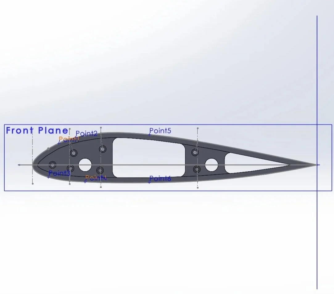
• Design a unique airfoil geometry optimized for aerodynamic performance
• Model the airfoil in CAD with a 6-inch chord length for 3D printing
• Conduct wind tunnel testing using pressure measurements along the surface
• Evaluate lift and drag performance across multiple angles of attack to assess efficiency and stability
-

Approach
• Used a pitot-static tube to measure airspeed in the wind tunnel via total and static pressure differences
• Integrated pressure taps at the stagnation point and multiple locations on the upper and lower airfoil surfaces
• Connected each tap through the hub to a pressure sensor for data acquisition
• Applied a calibration equation to convert measured voltages into pressure values for analysis
-
Solution
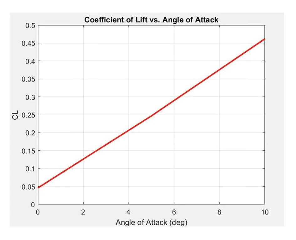
• Showed theory-consistent behavior for the coefficient of lift vs. angle of attack
• Displayed an approximately linear relationship from 0° to 10°, with a peak lift coefficient of 0.46
• Demonstrated a smooth increase in lift without premature stall behavior
• Confirmed a successful airfoil design with stable, reliable, and predictable lift performance within the tested range
Volt-veil
-
Challenge
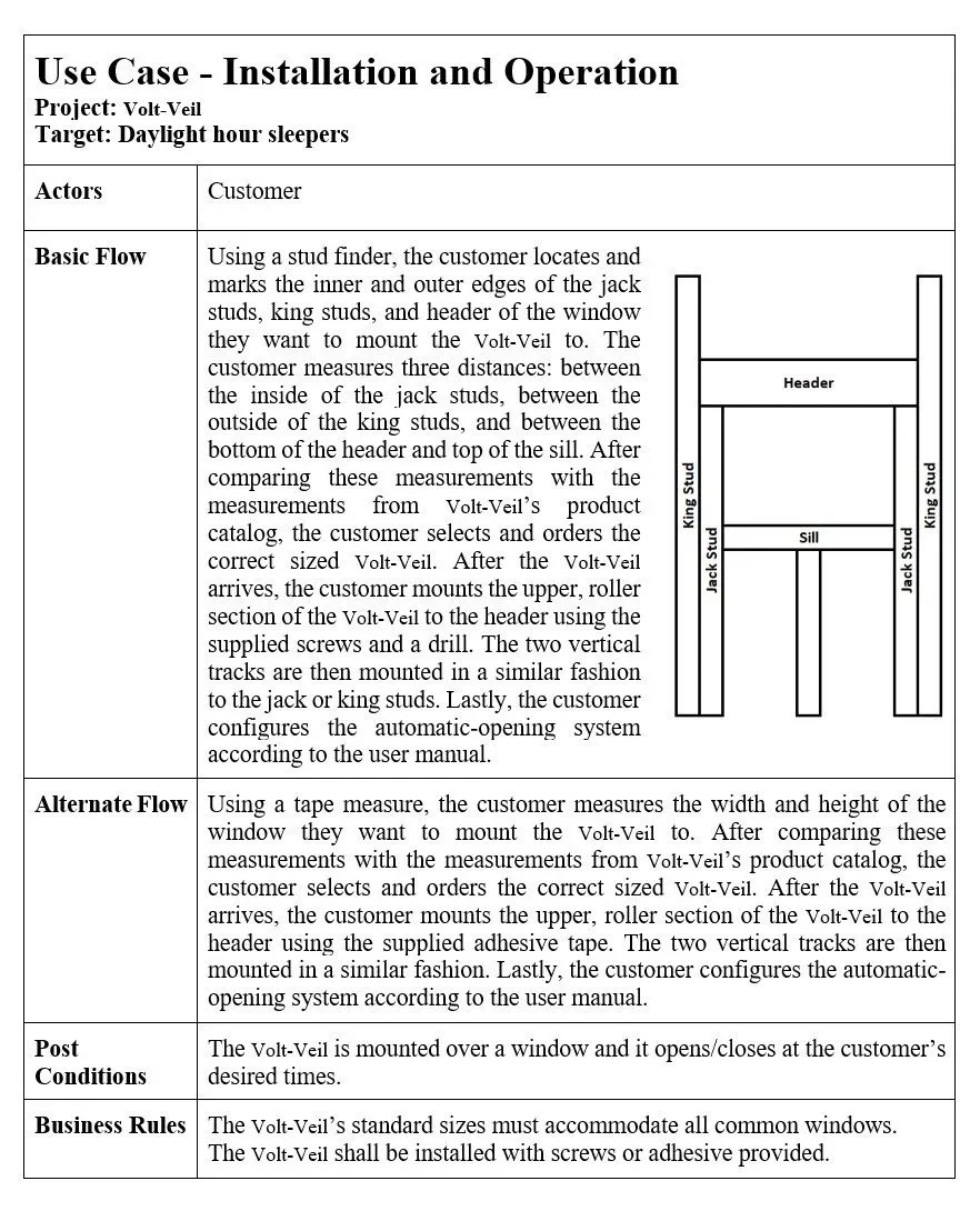
• Identify and evaluate market opportunities through brainstorming, weekly observations, and targeted questions to uncover unmet customer needs
• Apply design and feasibility criteria to narrow potential product ideas
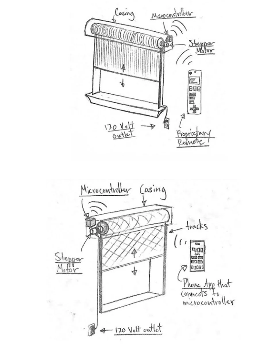
• Select Volt-Veil, a zero light-bleed, automatic curtain system, for its large market potential and low competition
• Conduct market analysis through customer surveys to define the product’s mission, target users, and design requirements for successful development
-
Approach
• Planned and managed the project using structured tools such as a Gantt Chart, DSM Chart, and resource allocation table to define timelines, responsibilities, and dependencies
• Identified customer needs through surveys and analysis, translating them into measurable target specifications and a Quality Function Deployment (QFD) matrix
• Developed and evaluated design concepts using structured methods including concept generation, concept screening/scoring, and Failure Modes & Effects Analysis (FMEA) to select the most viable solution
-
Solution
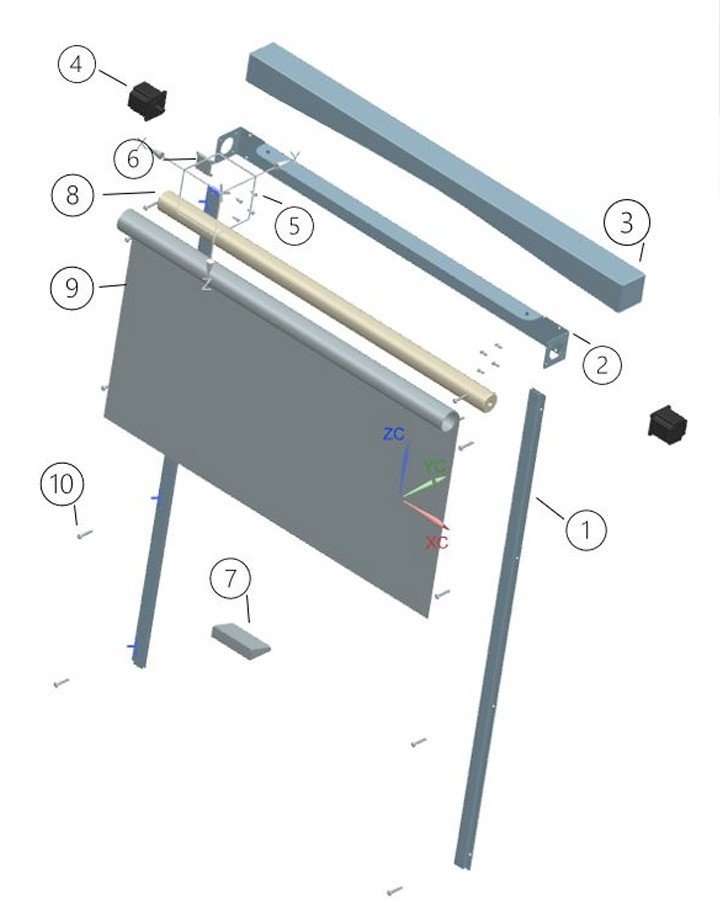
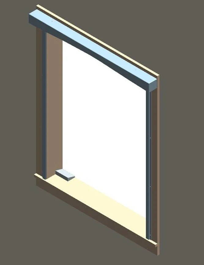
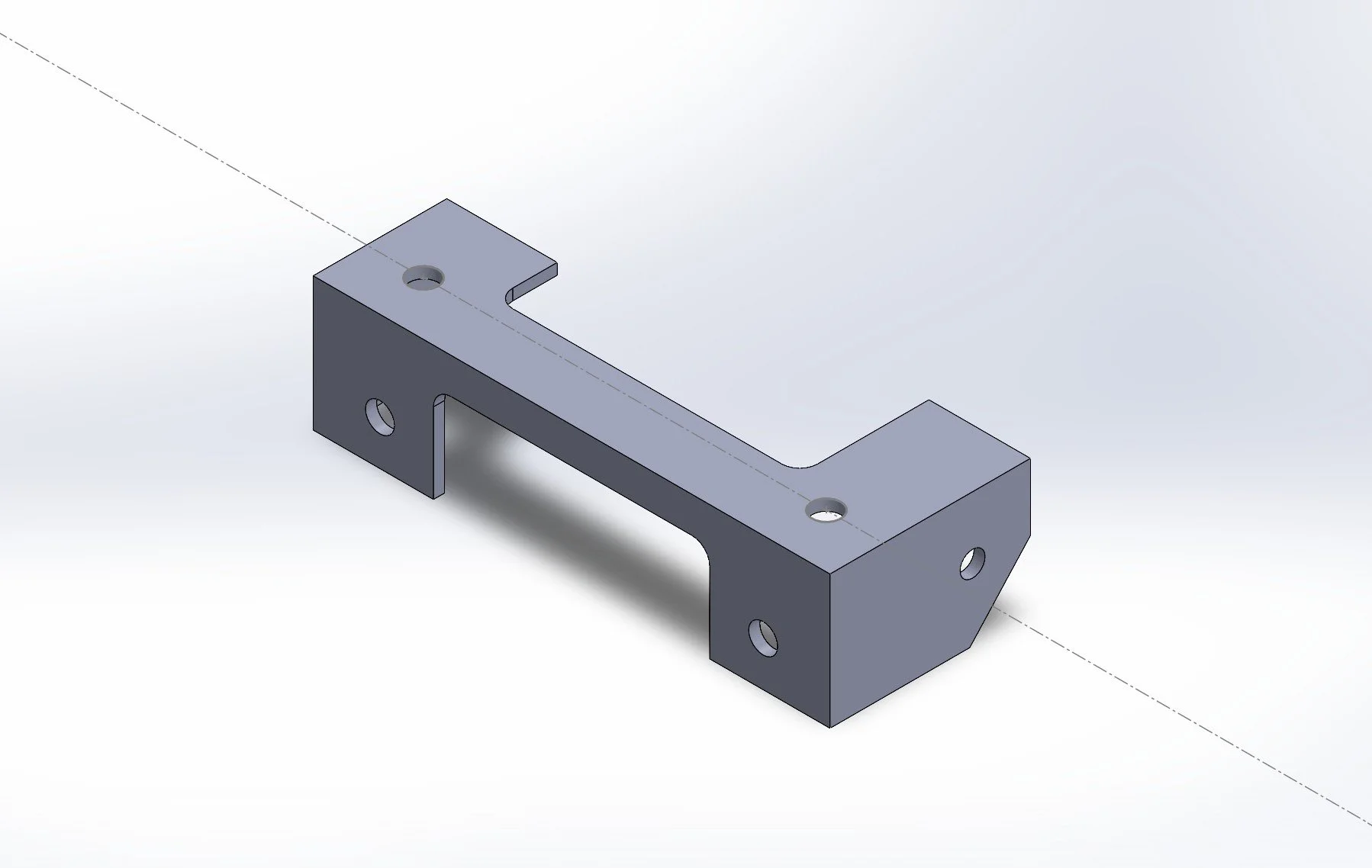
• Utilized CAD modeling to design, prototype, and refine the curtain’s mechanical and housing components for manufacturability
• Integrated a stepper motor, microcontroller, and programmable timer to enable automatic opening and closing based on user preferences
• Validated performance through assembly analysis, cost evaluation, and functional testing, confirming reliable operation and market feasibility


parking brake system
-

Challenge
• Must hold the fully loaded car on dry pavement against a 10% weight force without wheel chocks
• Operates independently from the main braking system and is excluded from main brake tests
• Must lock in place, be set from the seated, belted position in one motion, and stay engaged until intentionally released
• No tire or wheel-contact designs allowed—must fit within tight space constraint
-
Approach
• Used a pitot-static tube to measure airspeed in the wind tunnel via total and static pressure differences
• Integrated pressure taps at the stagnation point and multiple locations on the upper and lower airfoil surfaces
• Connected each tap through the hub to a pressure sensor for data acquisition
• Applied a calibration equation to convert measured voltages into pressure values for analysis
-
Solution
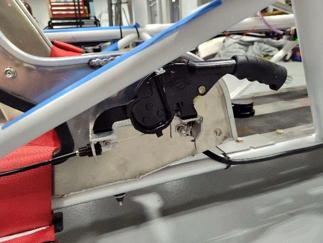
• Developed a parking brake system that fits within the vehicle’s tight space constraints and complies with all American Solar Challenge regulations
• Utilized a dedicated rear caliper mounted on the left rear wheel that is fully separate from the main braking system
• Featured a simple lever mechanism that locks securely in place and is easy to operate while fastened in the seat
• Successfully passed the 10% pull test, confirming that the brake can hold the fully loaded vehicle on dry pavement as required
Aeroshell ManufacTURING
-
Challenge
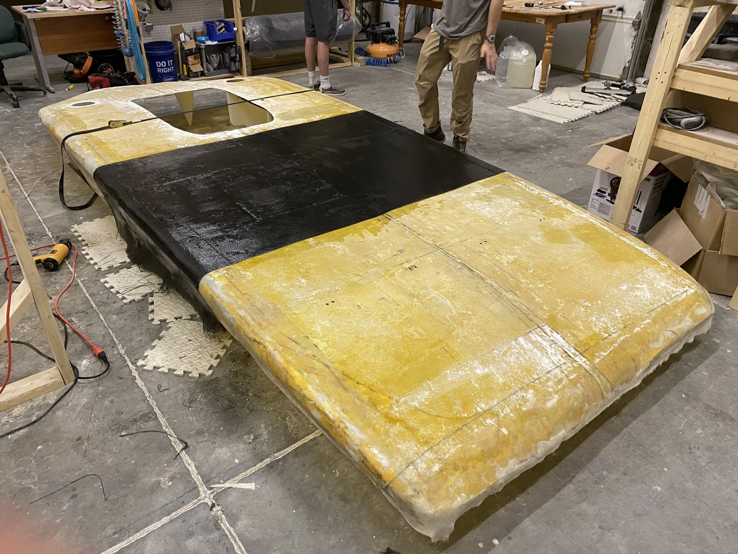
• The solar car aeroshell exhibited surface roughness, gaps, and misalignment between the top and bottom halves, causing significant aerodynamic drag and unstable airflow
• The shell was structurally weak and flexible making it difficult to remove or reassemble without damage.
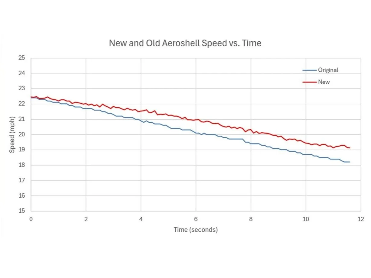
• These issues led to aerodynamic inefficiency during coast-down testing
-

Approach
• Undertook a remanufacturing process to rebuild the aeroshell using refined fiberglass layups and carbon fiber reinforcement to improve rigidity
• Focused on closing gaps between shell sections and ensuring smooth exterior surfaces for improved aerodynamic flow
• Prioritized durability and serviceability to make removal and maintenance of the aeroshell easier
-
Solution
• Successfully eliminated gaps and reduced surface imperfections
• The carbon-fiber-reinforced shell provided increased stiffness and improved handling during assembly and operation
• Coast-down testing confirmed a significant reduction in aerodynamic drag reflected by a measurable decrease in deceleration rate
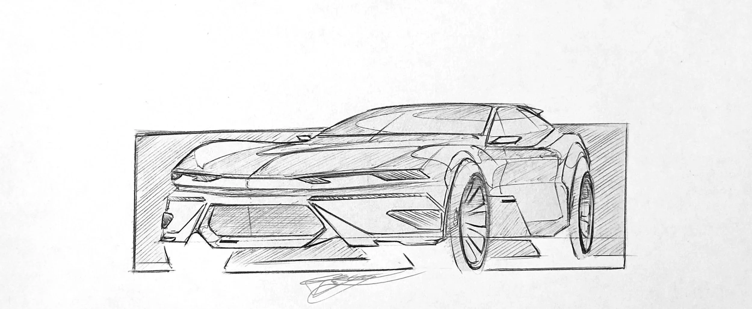
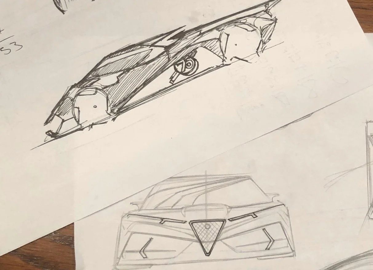
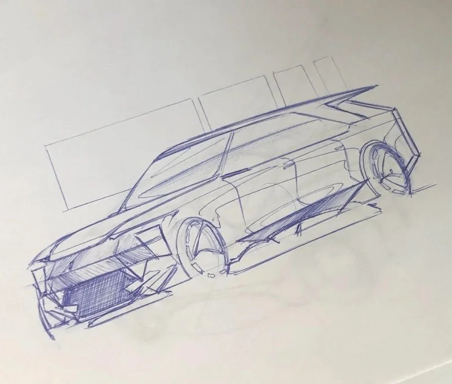
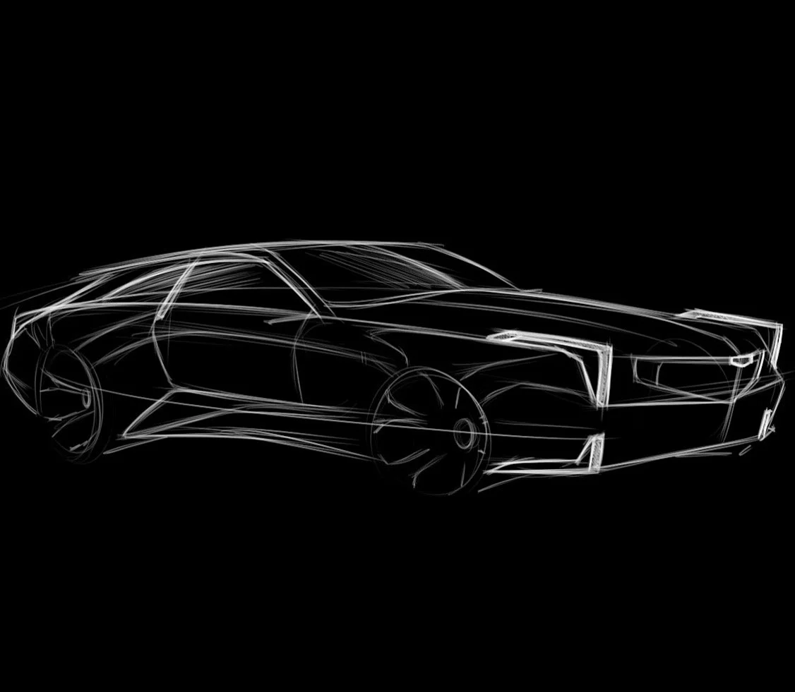
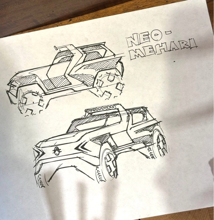
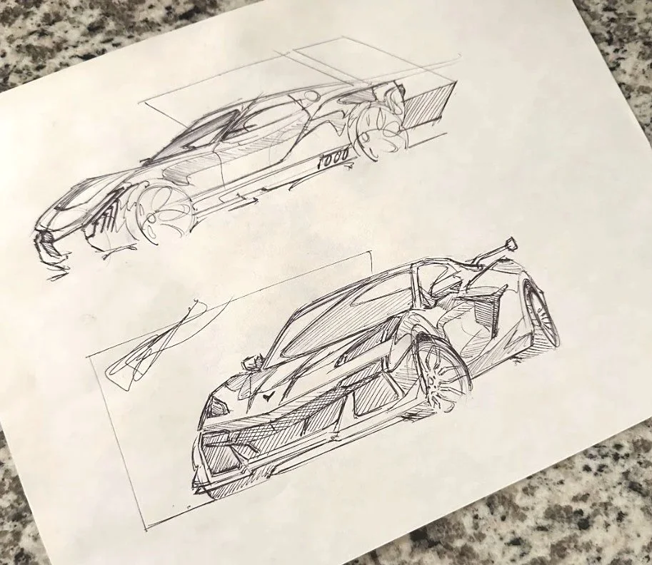
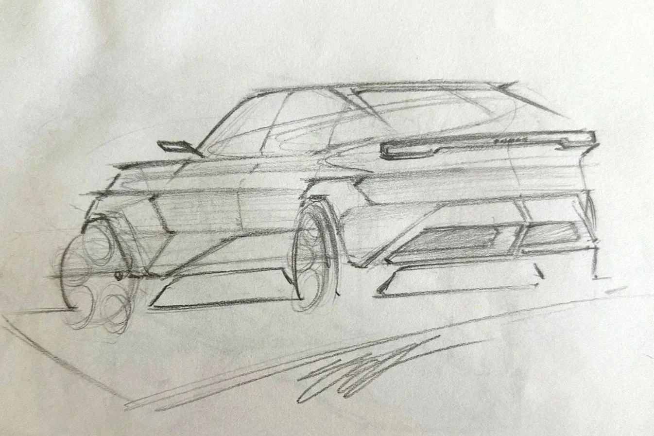
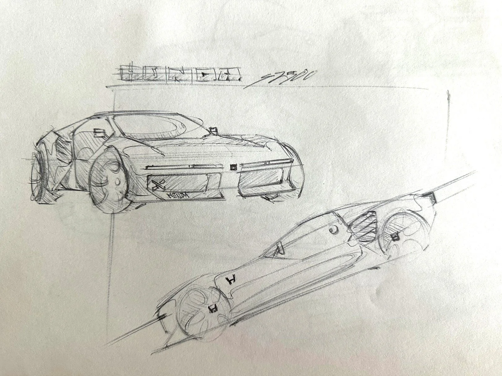
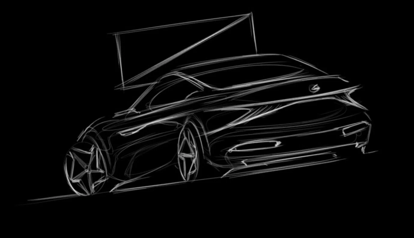
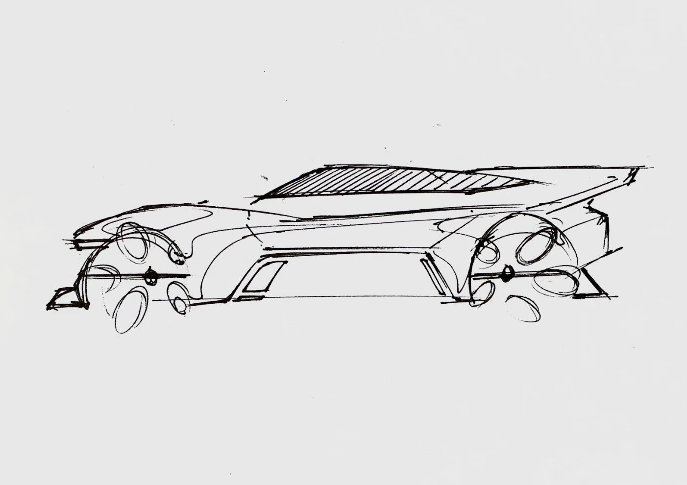
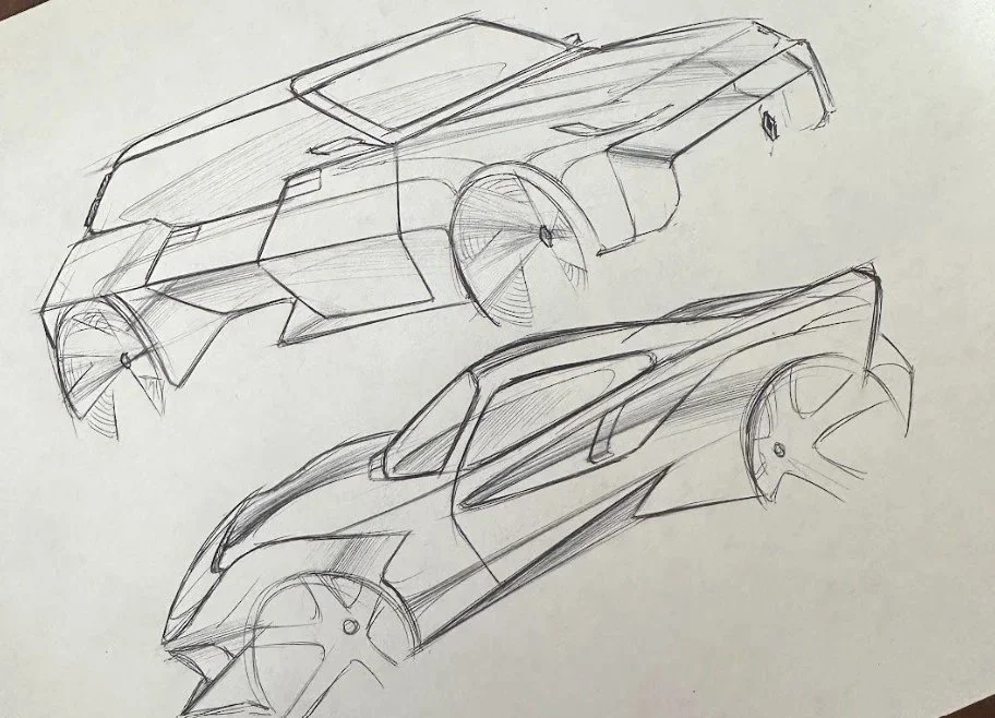
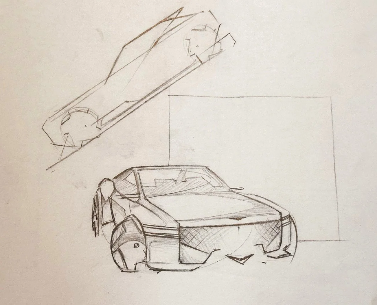
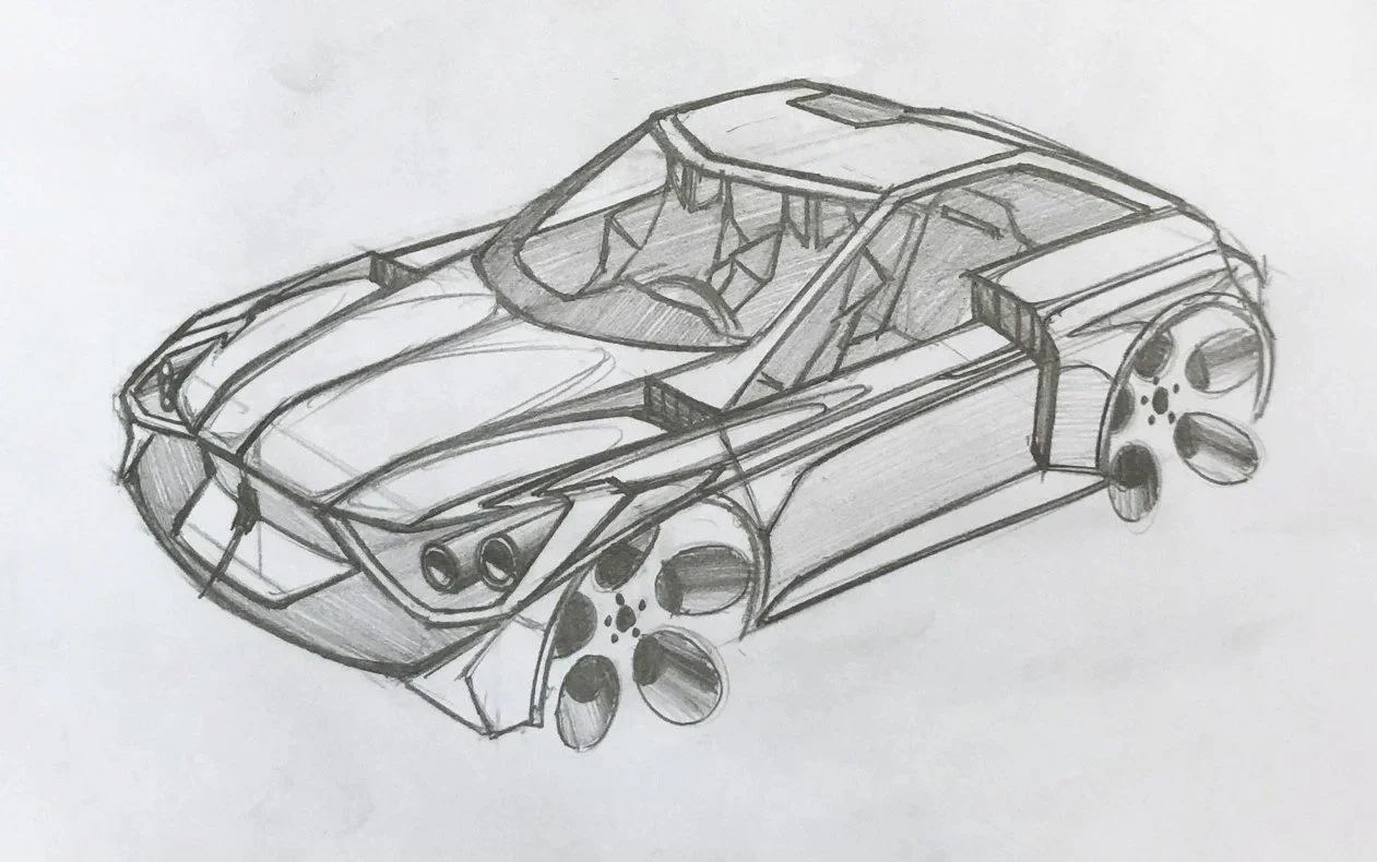
analog/digital automotive designs


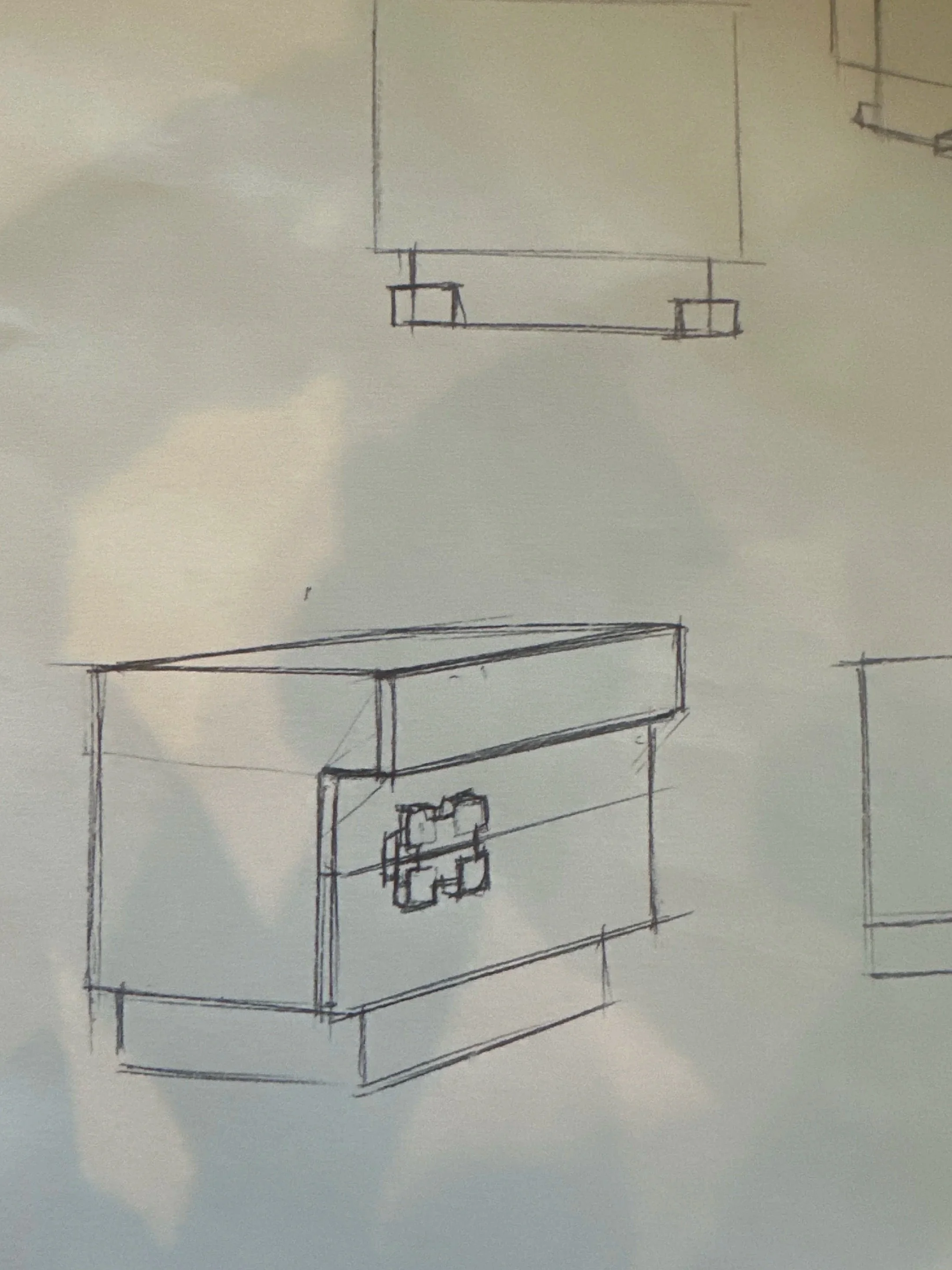
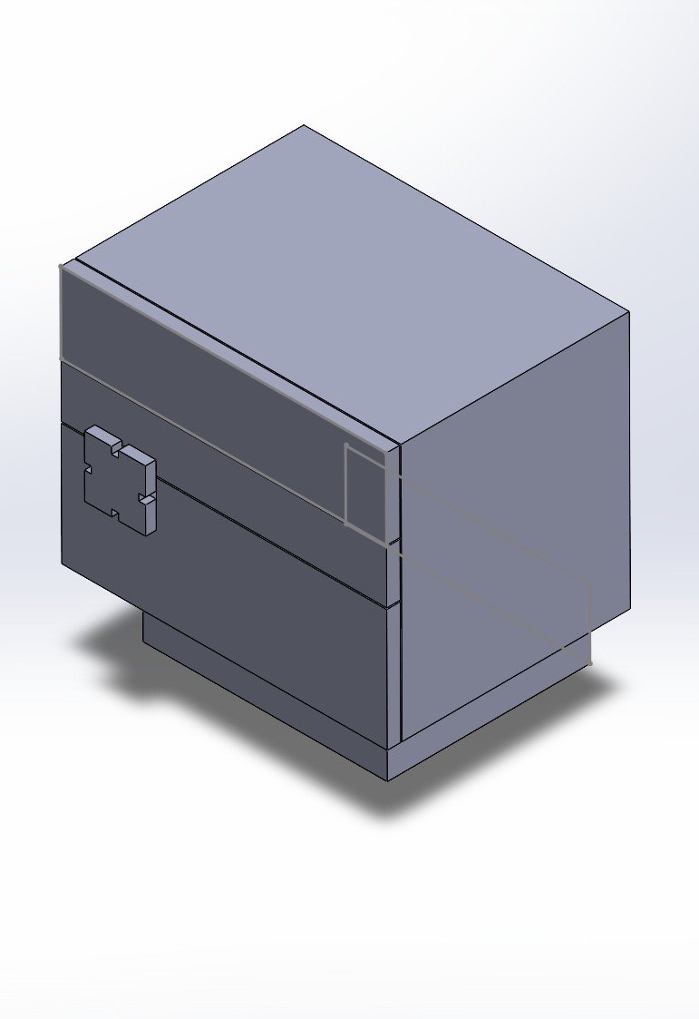
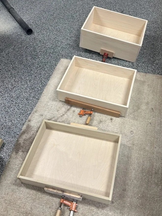
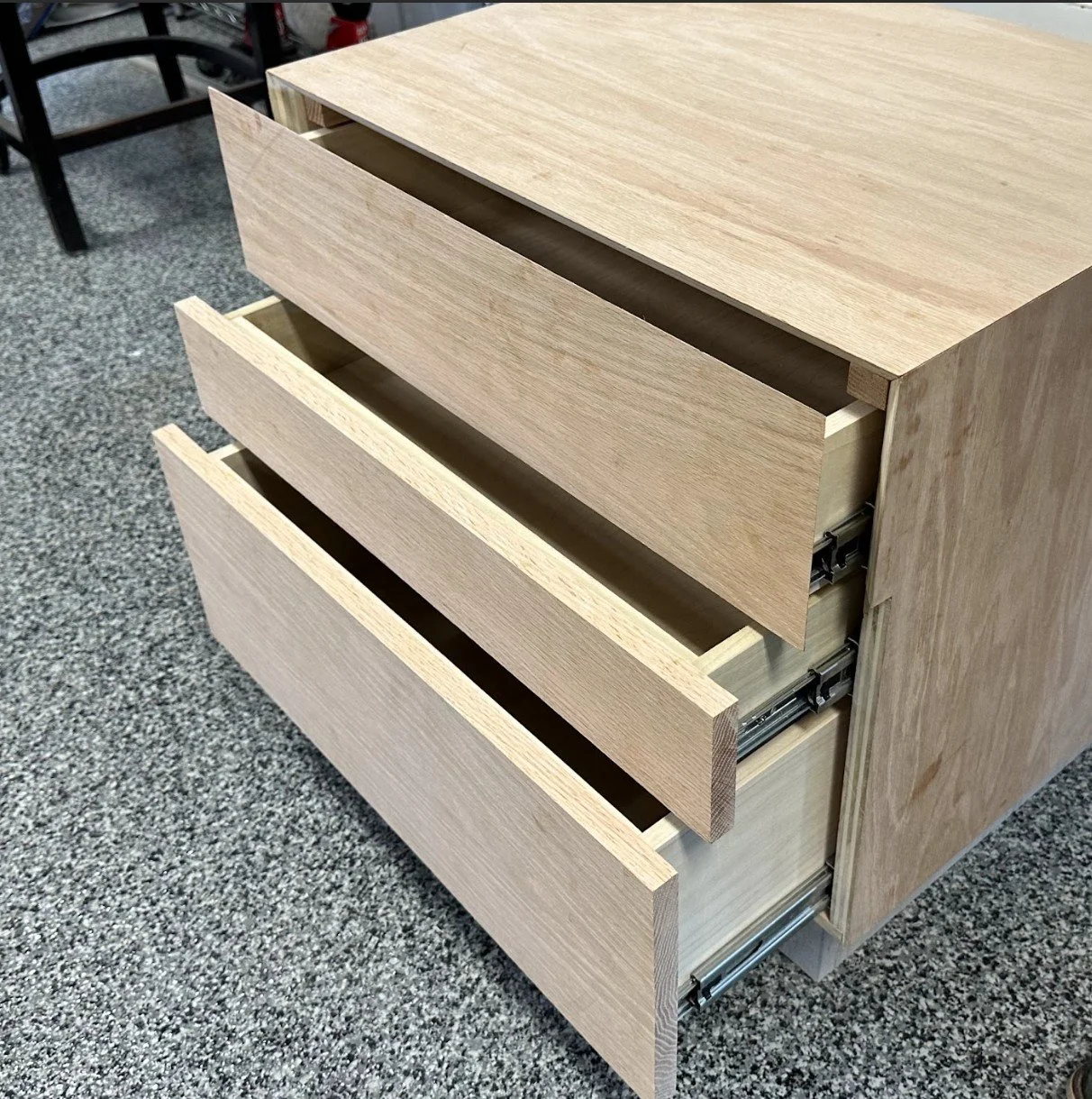
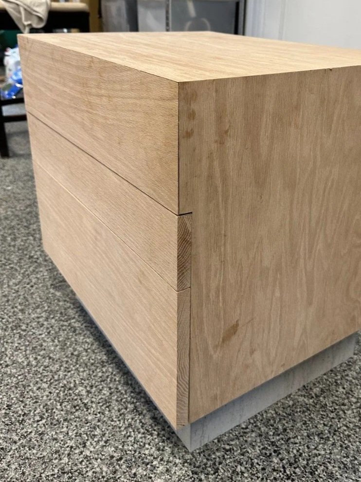
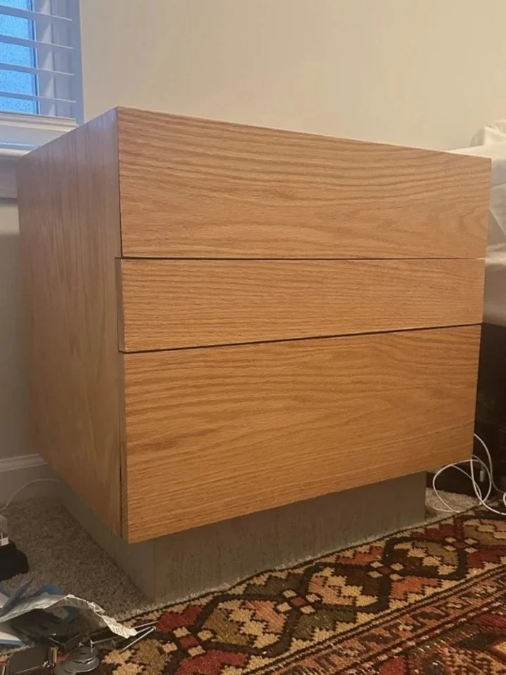
Brutalist Side Table
-
Challenge
• Create a mid-century modern/brutalist side table with solid woods and concrete
• Must feature 3 drawers—with the top drawer concealed to preserve brutalist look—and a large storage capacity
• All edges and seams must be precise and symmetrical
-
Approach
• Created a prototype in CAD to establish scaling and facade
• Used a miter saw, table saw, circular saw, and planar to cut solid white oak and pine
• Cut all of the top-drawer edges to 45 degrees to conceal it from all angles
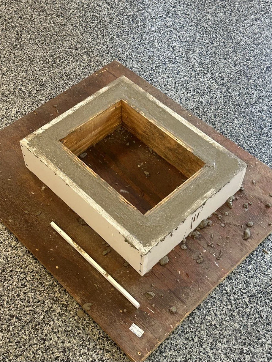
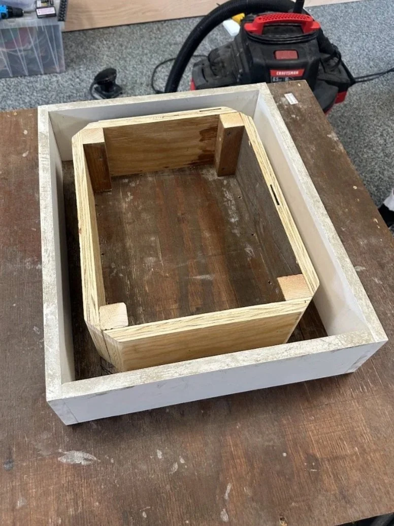
• Created hollow concrete base molds: one with 90-degree interior corners and one with 45-degree corners for concrete crack resistance
-
Solution
• All drawers have soft close rails and line up flush between each other with a minimal gap
• The second iteration concrete mold displayed resistance to cracks
• Implementation of veneer oak on the back face saved weight to increase mobility