
Modeling & Simulation
performance characterization
-

Challenge
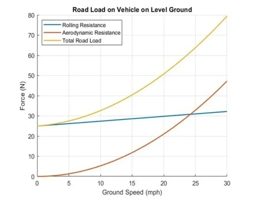
• Needed to simulate real-world road load forces on the vehicle to characterize aeroshell performance and determine optimal efficiency race speeds for competition
• Required an accurate method to quantify aerodynamic drag and rolling resistance under realistic driving conditions
• Faced difficulty in replicating on-road conditions in a controlled environment for reliable data collection
-

Approach
• Conducted multiple coast-down tests at varying speeds on a closed track to measure consistent deceleration profiles
• Used collected data to determine EPA road load coefficients for analysis
• Inputted these coefficients into MATLAB for simulation to model and analyze vehicle performance
-
Solution
• Developed a validated MATLAB model that accurately simulates vehicle deceleration and predicts road load behavior
• Identified optimal efficiency speeds for competition scenarios based on simulated energy consumption
• Enabled the team to optimize race strategy and speed targets, improving overall vehicle efficiency and performance
Transient tire control loop
-
Challenge
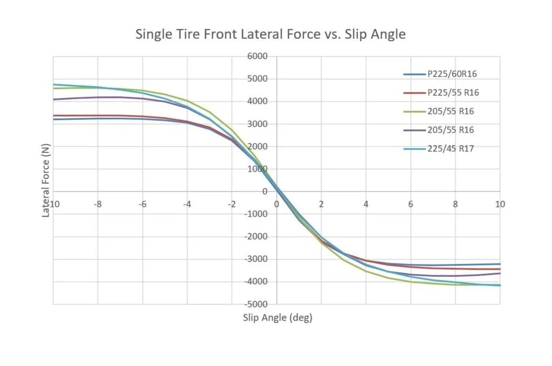
• Capture distinct front and rear tire responses to steering inputs and varying slip angles using the Pacejka formula
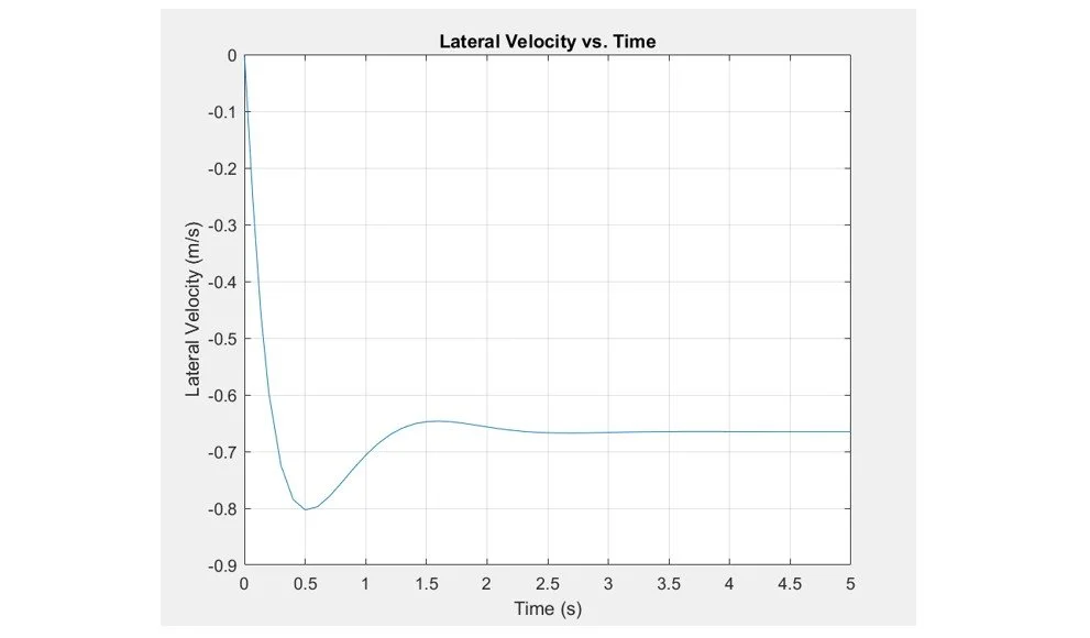
• Accurately simulate a vehicle’s transient lateral dynamics (lateral velocity and yaw rate)
• Integrate the tire models into a closed-loop system to predict behavior and design a controller that manages slip angles during transients
-

Approach
• Implemented the Pacejka “Magic Formula” to derive lateral force vs. slip-angle curves and dynamic stiffness for tire behavior
• Implemented a MATLAB Simulink control loop that uses slip-angle inputs (via steering model), measures lateral velocity and yaw rate, and provides closed-loop feedback for transient response testing
-
Solution
• Produced transient simulations showing time histories of lateral velocity and yaw rate for representative maneuvers, revealing dynamic overshoot and settling behavior
• Validated model behavior by checking consistency with expected Pacejka forces and sensitivity to front/rear tire parameter changes
• Used the simulation to inform control strategy, handling tradeoffs (understeer/oversteer tuning), and vehicle setup changes for real-world implementation
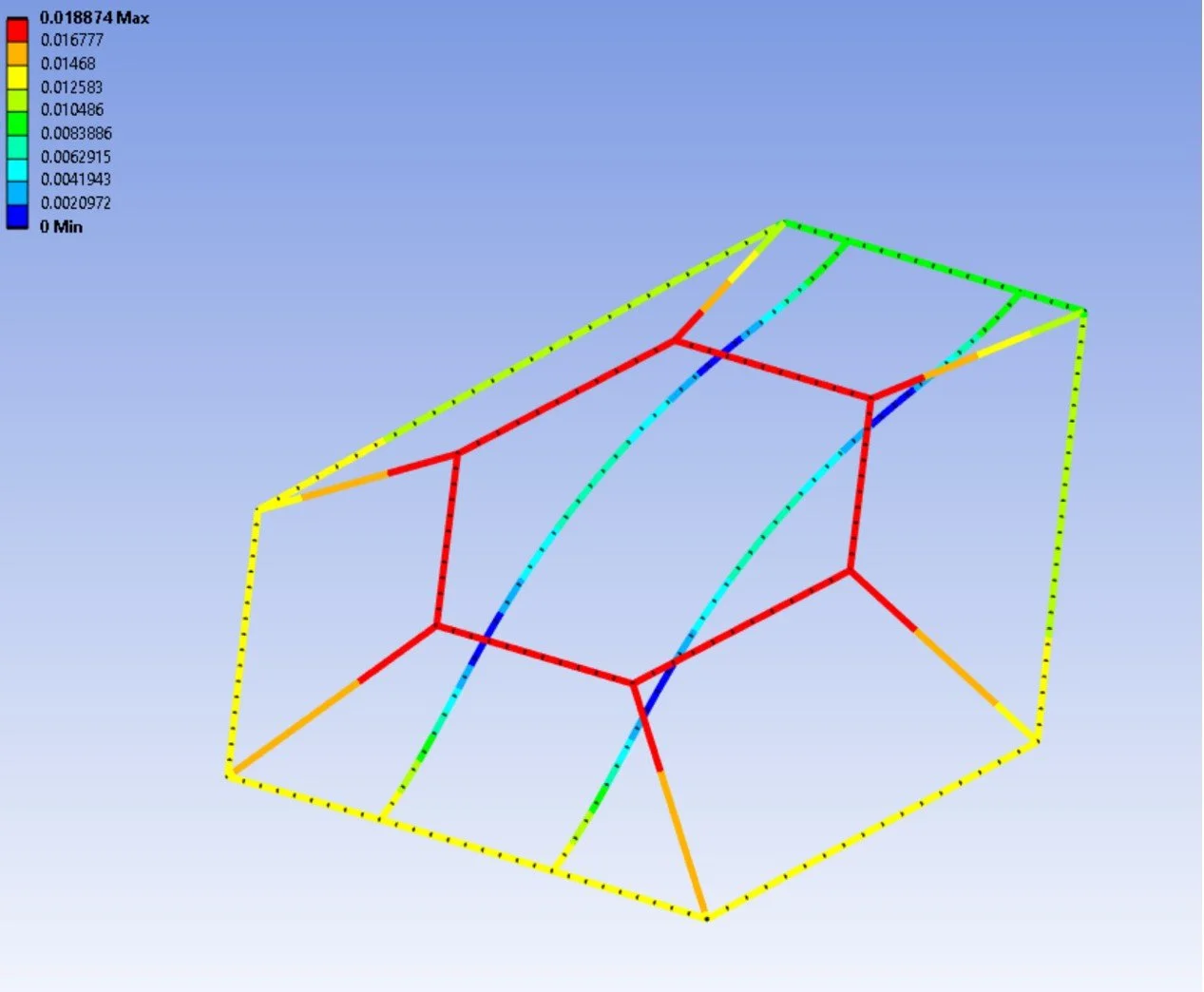
Constrained flight load frame Finite element analysis
-
Challenge
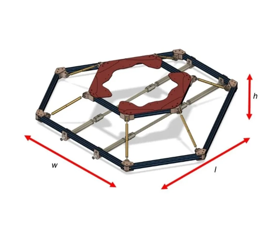
• Predict the static structural response of a UAV flight load frame to support evaluation and redesign
• Accurately estimate deflection, stress, and strain in critical structural sections to ensure the frame meets multiple competing design criteria: yield safety factor, buckling, deflection limits, and signal-to-noise ratio
• Balance conflicting performance goals—achieving the required 100:1 signal-to-noise ratio without exceeding yield or buckling limits of the load cells
-

Approach
• Conducted mechanical design hand calculations to establish baseline estimates and constraints
• Developed and iterated finite element models using Ansys Workbench with refined beam and truss meshing strategies to capture critical stresses and deflections
• Applied realistic boundary conditions and load cases derived from test data and material specifications
• Compared results from mechanical and FEA solutions to validate model assumptions and locate critical failure zones
-
Solution
• Identified that the original prototype did not meet 3 of 4 design criteria, failing the signal-to-noise ratio requirement but close on yield and buckling margins
• Re-designed the load frame to significantly improve yield strength safety factor (7.97) and deflection performance, while boosting SNR by 50%
• Accepted a controlled trade-off by reducing the buckling factor of safety to 2.01, still within a manageable range
• Identified further improvement opportunities through material changes or modifying load cell geometry to enhance both strength and SNR in future iterations
Electric vehicle EPA test cycle model
-

Challenge
• Accurately model the 2025 Rolls-Royce Spectre’s electric powertrain and vehicle performance using simulation data and validate results against real-world EPA and manufacturer data
• Quantify the impact of vehicle parameters such as mass, drag coefficient, and efficiency on energy consumption, range, and acceleration.
• Resolve discrepancies between published performance data (0–60 mph times and power output) while maintaining modeling accuracy under various test conditions
-

Approach
• Compiled stock vehicle data and implemented performance modeling within in Excel
• Validated model outputs against EPA Wh/mi data and manufacturer specs
Performed sensitivity analyses by varying vehicle weight (GVWR), aerodynamic drag (Cd), and grade to observe changes across drive cycles (UDDS, HwFET, and US06)
-

Solution
• Achieved close agreement between modeled and actual data (<2% deviation) to confirm model accuracy
• Identified mass reduction of 500 kg as the most impactful optimization—yielding an 11% efficiency improvement and 10% range increase (~40 extra miles)
• Found that aerodynamic improvements (Cd = 0.18) offered notable highway benefits (13% range gain) but limited city performance improvement